5. Functionality
5.1. Light LVDS panel (TP070C01)
Connection
Connect the LVDS panel to VAB-600 via VAB-600-D card.
U-Boot
Connect VAB-600 and host PC through COM port. Update uboot parameters as below:
setenv wmt.display.param 2:0:24:800:480:60
setenv bootargs-common console=ttyS0,115200n8 console=tty0 init=/init
saveenv
reset
800:480 is the LVDS panel resolution. Please replace it with the LVDS panel resolution that you use.
Xorg
Edit /etc/X11/xorg.conf in Debian to support LVDS panel display. Delete # to select the annotated timing for LVDS panel:
# Modeline "1440x900" 106.50 1440 1528 1672 1904 900 903 909 934 -hsync +vsync
# Modeline "1920x1080" 173.00 1920 2048 2248 2576 1080 1083 1088 1120 -hsync +vsync
Modeline "800x480" 33.5 800 964 974 1063 480 490 500 523
So does the display resolution for LVDS panel:
Section "Screen"
  Identifier    "Mali Screen"
  Device        "Mali FBDEV"
  Monitor       "Mali Monitor"
  DefaultDepth  16
  SubSection "Display"
    Depth 16
    # Modes "1024x768" "800x600"
    Modes "800x480"
  EndSubSection
EndSection
Note
Notice that to light LVDS panel, you have to modify both U-Boot and Xorg, lack of any step of them may probably cause the failure to display the LVDS panel.
5.2. Light TTL panel (LW700AT9901)
Connection
Connect the TTL panel to VAB-600 via VAB-600-C card.
U-Boot
Connect VAB-600 and host PC through COM port. Update uboot parameters as below:
setenv wmt.display.param 2:1:24:800:480:60
setenv bootargs-common console=ttyS0,115200n8 console=tty0 init=/init
saveenv
reset
800:480 is TTL panel resolution. Please replace it with the TTL panel resolution that you use.
Xorg
Edit /etc/X11/xorg.conf in Debian to support TTL panel display. Delete # to select the annotated timing for TTL panel:
# Modeline "1440x900" 106.50 1440 1528 1672 1904 900 903 909 934 -hsync +vsync
# Modeline "1920x1080" 173.00 1920 2048 2248 2576 1080 1083 1088 1120 -hsync +vsync
Modeline "800x480" 33.5 800 964 974 1063 480 490 500 523
So does the display resolution for TTL panel:
Section "Screen"
  Identifier    "Mali Screen"
  Device        "Mali FBDEV"
  Monitor       "Mali Monitor"
  DefaultDepth  16
  SubSection "Display"
    Depth 16
    # Modes "1024x768" "800x600"
    Modes "800x480"
  EndSubSection
EndSection
Note
Notice that to light TTL panel, you have to modify both U-Boot and Xorg, lack of any step of them may probably cause failure to display the TTL panel.
5.3. Light Dual Channel LVDS panel (AUOG220SVN01.0)
Connection
Connect the dual channel LVDS panel to VAB-600 via VAB-600-D card.
U-Boot
Connect VAB-600 and host PC through COM port. Update uboot parameters as below:
setenv wmt.display.param 2:0:24:1680:1050:60
setenv bootargs-common console=ttyS0,115200n8 console=tty0 init=/init
saveenv
reset
1680:1050 is dual channel LVDS panel resolution. Please replace it with the dual channel LVDS panel resolution that you use.
Xorg
Edit /etc/X11/xorg.conf in Debian to support dual channel LVDS panel display. Delete # to select the annotated timing for dual channel LVDS panel:
# Modeline "1920x1080_75" 220.75 1920 2064 2264 2608 1080 1083 1088 1130 -hsync +vsync
Modeline "1680x1050" 146.25 1680 1784 1960 2240 1050 1053 1059 1089 -hsync +vsync
# Modeline "640x480" 23.75 640 664 720 800 480 483 487 500 -hsync+vsync
So does the display resolution for dual channel LVDS panel:
Section "Screen"
  Identifier   "Mali Screen"
  Device       "Mali FBDEV"
  Monitor      "Mali Monitor"
  DefaultDepth 16
  SubSection "Display"
    Depth 16
    # Modes "1024x768" "800x600"
    Modes "1680x1050"
  EndSubSection
EndSection
Note
Notice that to light dual channel LVDS panel, you have to modify both UBoot and Xorg, lack of any step of them may probably cause failure to display the TTL panel.
5.4. Light HDMI monitor
U-Boot
Connect VAB-600 and host PC through COM port. Update uboot parameters as below:
setenv wmt.display.param 4:6:1:1920:1080:60
setenv bootargs-common console=ttyS0,115200n8 console=tty0 init=/init
saveenv
reset
1920:1080 is HDMI monitor resolution. Actually it will detect EDID information automatically and choose the maximum resolution, therefore the setting influences U-Boot logo resolution only.
Xorg
Edit /etc/X11/xorg.conf` in Debian to support HDMI monitor display. Add ``# to annotate the timing for LDS panel:
# Modeline "1440x900" 106.50 1440 1528 1672 1904 900 903 909 934 -hsync +vsync
# Modeline "1920x1080" 173.00 1920 2048 2248 2576 1080 1083 1088 1120 -hsync +vsync
# Modeline "800x480" 33.5 800 964 974 1063 480 490 500 523
So does the display resolution for HDMI:
Section "Screen"
  Identifier   "Mali Screen"
  Device       "Mali FBDEV"
  Monitor      "Mali Monitor"
  DefaultDepth 16
  SubSection   "Display"
    Depth 16
    # Modes "1024x768" "800x600"
    # Modes "800x480"
  EndSubSection
EndSection
Note
Notice that to light HDMI monitor normally, you have to modify both UBoot and Xorg, lack of any step of them may probably cause the failure to display the HDMI monitor
5.5. Switch HDMI mode by xrandr tool
In order to switch Mode, we use xrandr command to switch the resolution and refresh rate of the monitor.
For example, to list all the supporting modes, we usually run xrandr -q or xrandr --verbose.
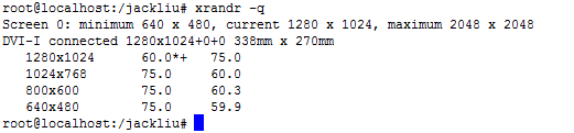
Figure 1: Example xradr output
To switch resolution and refresh rate, such as “800x600@75”, we usually run:
xrandr --output DVI-I --mode 800x600 --rate 75
The option --output DVI-I must be added and does not need to be changed for every resolution change xrandr command.
Currently, we only support the display modes that are listed in the following table. xrandr -q command shows the combination/subset of the mode your display device support (from EDID) and the mode in the following table. Please do not set --mode outside of the result of xrandr -q, the -- rate can only be followed by 60 or 75. If you can see refresh rate 59.9, just set it 60.
| Resolution | Color Depth | 60Hz Refresh | 75Hz Refresh |
|---|---|---|---|
| 640x480 | 16/32bit | ✓ | ✓ |
| 800x480 | 16/32bit | ✓ | |
| 800x600 | 16/32bit | ✓ | ✓ |
| 1024x768 | 16/32bit | ✓ | ✓ |
| 1280x720 | 16/32bit | ✓ | |
| 1280x768 | 16/32bit | ✓ | |
| 1280x1024 | 16/32bit | ✓ | ✓ |
| 1360x768 | 16/32bit | ✓ | |
| 1400x1050 | 16/32bit | ✓ | |
| 1440x900 | 16/32bit | ✓ | ✓ |
| 1680x1050 | 16bit | ✓ | |
| 1920x1080 | 16bit | ✓ |
5.6. Change Color Depth/bpp.
Please open /etc/X11/xorg.conf and change DefaultDepth to 16 or 24 to change the Color Depth. You must restart the x-window, so the change can take effect.
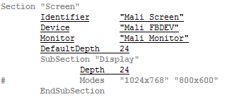
Figure 2: Color depth setting
5.7. Multimedia local playback
Currently we support MPEG1, MPEG2, MPEG4 (except MSMPEGv1/v2), WMV9/VC1, H264 HW acceleration. Play local multimedia files by the following command:
gst-launch-0.10 playbin uri=file:/<path-and-file-name>
Or:
totem <path-and-file-name>
5.8. Audio adjustment
To modify the settings of audio, open a terminal and modulate alsamixer:
alsamixer
The following figure shows a fine-tuned result of alsamixer.
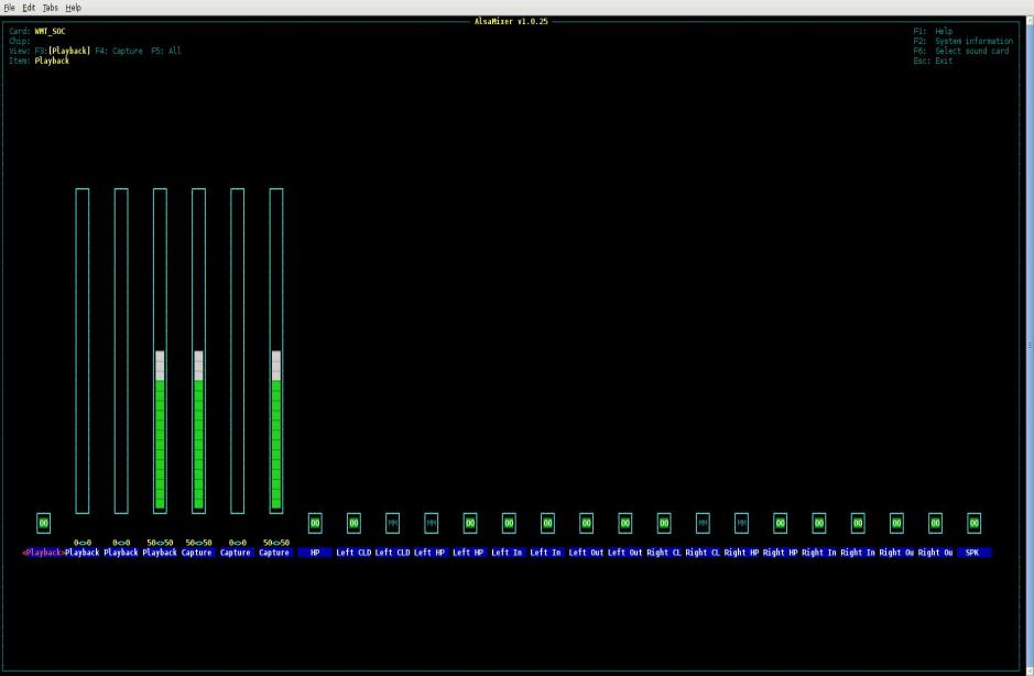
Figure 3: Alsamixer screenshot
Click ← (left) or → (right) to choose the item to be modified. Press M to turn on or turn off an option (mute), and click ↓ (down) or ↑ (up) to subtract or add the value.
To enable PCM audio volume control, asound.conf must be reloaded.
To achieve this goal, install the necessary packages first:
apt-get install alsa-utils
Then operate the playing action to initialize the configurations in asound.conf:
speaker-test –Dsoftvolume –c2 -twav
After it outputs the test music for several seconds, use CTRL+C to stop the examination. Next step is to open alsamixer again, check whether PCM audio volume control appears or not.
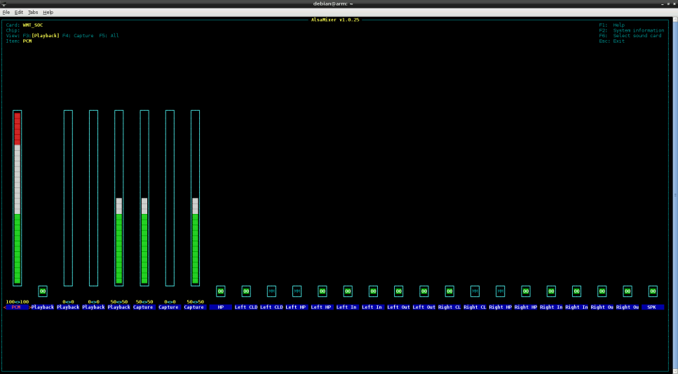
Figure 4: Alsamixer check
The name of PCM audio volume control is PCM. Change its value to observe if the volume alters.
5.9. GPIO control
This section describes how to operate GPIO function. Please use devmem2 utility to access GPIO, which was pre-installed in the file system image. If you need to change kernel configurations, please refer to VAB-600_Linux_defconfig in /BSP/Kernel_Source_Codes/ to ensure the GPIO function.
5.9.1. GPIO hardware design
The GPIO function was provided by CN9 “GPIO / SMBus Interface Pin Header”. They are mapped to GPIO20 ~ GPIO27. The corresponding pins in VAB-600 are listed in the following figures.
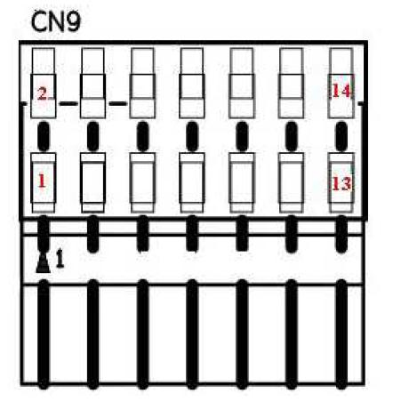
Figure 5: GPIO header
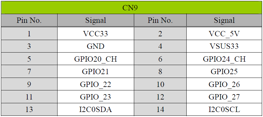
Figure 6: GPIO pinout
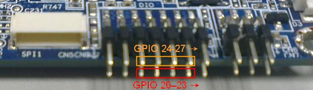
Figure 7: GPIO circuit view
You can connect your own device to the pins and operate it via the relative GPIO settings. To manage the particular GPIO, the homologous register values have to be changed.
5.9.2. devmem2 utility
This utility can also be installed in Linux official distribution. Use devmem2 utility to read/write GPIO registers:
devmem2 [address] [type] [data]
Where:
address : physical address of the register
type : data type to be read/written, [b]yte, [h]alfword or [w]ord
data : data to be written to the register
5.9.2.1. devmem2 utility read and write
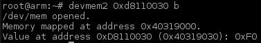
For example, if you want to read the register 0xd8110030 in byte format, you must type the command below:
devmem2 0xd8110030 b
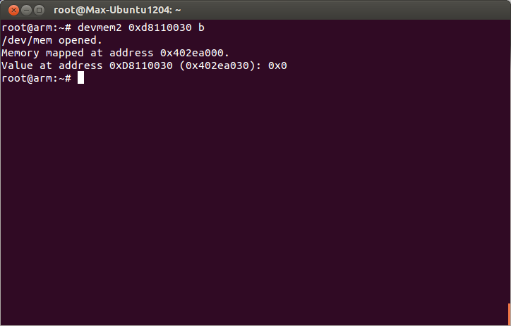
Figure 8: devmem2 read operation
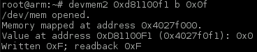
Same for the writing operation, write 0xff value to the register 0xd81100b0 in byte format with the coming order:
devmem2 0xd81100b0 b 0xff
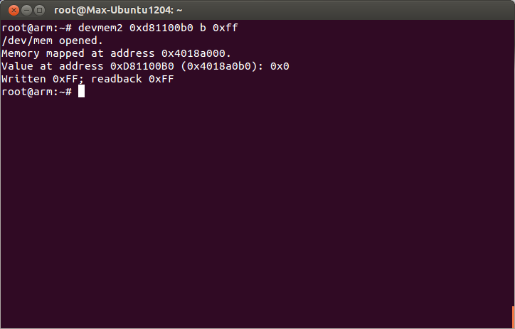
Figure 9: devmem2 write operation
For detailed descriptions of GPIO register values, please refer to Appendix A. Q&A.
5.9.3. Test GPIO input and output
5.9.3.1. Test GPIO connection
In this test, GPIO 20-23 are connected to GPIO 24-27. Once the state of GPIO 20–23 are changed, GPIO 24–27 also turn to be the same situation, and vice versa. In other words, this phenomenon means that the influence you do to one part may change another side.
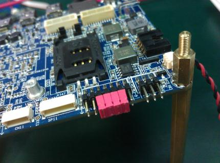
Figure 10: GPIO testing
Besides, before everything starts, you had batter clean the relative registers:
devmem2 0xd81100b0 b 0x0
devmem2 0xd81100b1 b 0x0
devmem2 0xd81100f0 b 0x0
devmem2 0xd81100f1 b 0x0
5.9.3.2. Set GPIO 20-23 to change GPIO 24-27
The first step is to examine the value of GPIO 24-27 input data register value (read GPIO 24-27 input registers):
devmem2 0xd8110031 b
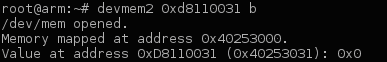
Obviously, the value should be 0x0.
To begin the experiment, set the value of GPIO 20-23 output enable registers to be high state (write GPIO 20-23 output enable registers):
devmem2 0xd81100b0 b 0xf0
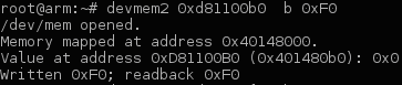
Then set the value of GPIO 20-23 output data registers also to be high state (write GPIO 20-23 output data registers):
devmem2 0xd81100f0 b 0xf0
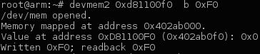
Now GPIO 20-23 should output the high state, which changes the low state of GPIO 24-27 to be high state.
Examine the value of GPIO 24-27 input data register value (Read GPIO 24-27 input Registers):
devmem2 0xd8110031 b
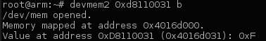
The value should be 0xF because of the influence of GPIO 20-23.
5.9.3.3. Set GPIO 24-27 to change GPIO 20-23
The first step is to examine the value of GPIO 20-23 input data register value (read GPIO 20-23 input registers):
devmem2 0xd8110030 b
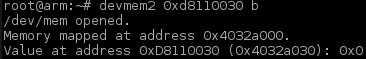
Obviously, the value should be 0x0.
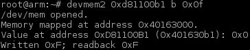
To begin the experiment, set the value of GPIO 24-27 output enable registers to be high state (write GPIO 24-27 output enable registers):
devmem2 0xd81100b1 b 0x0f
Then set the value of GPIO 24-27 output data registers also to be high state (write GPIO 24-27 output data registers):
devmem2 0xd81100f1 b 0x0f
Now GPIO 24-27 should output the high state, which changes the low state of GPIO 20-23 to be high state.
Examine the value of GPIO 20-23 input data register value (read GPIO 20-23 input registers):
devmem2 0xd811003b b
The value should be 0xF because of the influence of GPIO 24-27.
5.10. External RTC control
This section describes how to operate external RTC function. Please use i2c-tools utility to access external RTC, which was pre-installed in the file system image. If you need to change kernel configurations, please refer to VAB-600_Linux_defconfig in BSP/Kernel_Source_Codes/ to ensure the external RTC function.
5.10.1. External RTC hardware design
The external RTC IDT1337G was controlled by VAB-600 via I2C0 bus. The slave address of IDT1337G is 0x68 and it supports 16 timekeeper registers. The IDT1337G supports auto power-on control by using alarm2 and INTB pin.
5.10.2. Display external RTC timekeeper registers

Figure 19: Dumping the RTC register values
5.10.3. Set date and time to external RTC
The following commands list all the possibilities to set the external RTC:
i2cset -f -y 0 0x68 0x0 0x$(date +"%S") // seconds
i2cset -f -y 0 0x68 0x1 0x$(date +"%M") // minutes
i2cset -f -y 0 0x68 0x2 0x$(date +"%-k") // hours
i2cset -f -y 0 0x68 0x3 0x$(date +"%u") // day of week
i2cset -f -y 0 0x68 0x4 0x$(date +"%d") // date of month
i2cset -f -y 0 0x68 0x5 0x$(date +"%m") // month
i2cset -f -y 0 0x68 0x6 0x$(date +"%g") // year
i2cset -f -y 0 0x68 0xb 0x0 // alarm2 minutes
i2cset -f -y 0 0x68 0xc 0x0 // alarm2 hours
i2cset -f -y 0 0x68 0xd 0x0 // alarm2 day or date
i2cset -f -y 0 0x68 0xe 0x4 // disable alarm
i2cset -f -y 0 0x68 0xf 0x0 // clear alarm status
5.10.4. Test auto power-on control of external RTC
Configure alarm2 registers to enable auto power-on control. For example: set alarm each hour:
i2cset -f -y 0 0x68 0xb 0x0 // alarm2 minutes
i2cset -f -y 0 0x68 0xc 0x80 // alarm2 hours
i2cset -f -y 0 0x68 0xd 0x80 // alarm2 day or date
i2cset -f -y 0 0x68 0xf 0x0 // clear alarm status
i2cset -f -y 0 0x68 0xe 0x6 // enable alarm2
The register values 0x80 indicate “don’t care.” Only when minutes match (register value(0x1) == value(0xb)), alarm2 will set, A2F flag is at logic 1 and the INTB pin goes low.
After configuration, you will see the register values like below:

Figure 20: RTC set for auto power-on
If system time is 10:30 a.m., then the system will auto boot on 11:00 a.m., 12:00 p.m., 1:00 p.m. and so on.
After auto power-on, you will see the register values like below:

Figure 21: RTC register values after auto power-on
5.10.5. Disable alarm2 and clear alarm2 status of external RTC
Please remember to disable alarm2 and clear alarm2 status after booting the system every time. If you don’t disable alarm2 and alarm2 status isn’t clear, the system will boot right away after shutdown. If alarm2 status is clear but you don’t disable alarm2, the system will still boot on schedule even the system is running.
Disable alarm and clear alarm status:
i2cset -f -y 0 0x68 0xe 0x4 // disable alarm
i2cset -f -y 0 0x68 0xf 0x0 // clear alarm status
In order to boot on schedule, please remember to clear alarm2 status and enable alarm2 before shutdown.
Clear alarm status and enable alarm2:
i2cset -f -y 0 0x68 0xf 0x0 // clear alarm status
i2cset -f -y 0 0x68 0xe 0x6 // enable alarm2
When alarm2 status is not clear, if you enable alarm2 first without clearing alarm2 status then the system will auto boot after 5 seconds. In order to avoid this situation, you need to clear alarm2 status first, then enable alarm2.
5.11. WatchDog control
This section describes how to operate watch dog function. Please use watch dog utility (wdt_app) to access watch dog, which was pre-installed in the file system image. If you need to change kernel configurations, please refer to VAB-600_Linux_defconfig in BSP/Kernel_Source_Codes/ to ensure the watch dog function.
5.11.1. Enable the WatchDog
First of all, the watch dog must be enabled to carry out its tasks:
wdt_app -et
Without enabling WatchDog, the operations that are relative to WatchDog will not take any effect.

Figure 22: WatchDog enable
5.11.2. Set the WatchDog timer
Fill the value of the WatchDog timer in this step, decide when the watch dog can perform its function to restart the system:
wdt_app –t${second}
${second} means the period counting in seconds to reboot your machine, which should be within 0 to 256.
For example, you want the system to restart automatically in 180 seconds, the command format should look like the following:
wdt_app –t180

Figure 23: WatchDog timer
After 180 seconds, the machine will reboot by itself.
5.11.3. Get the WatchDog timer
Once you set the WatchDog timer, you may observe the value of the watch dog timer by this order:
wdt_app -tg
Its return value will show the number counting down in your watch dog, which indicates the remaining time before the system restarts.
For instance, in the last step you just set the watch dog timer to 180 seconds, you will see the value of the watch dog timer decreases.
Moreover, to print the return value, add echo $? to the input command

Figure 24: Get the WatchDog timer value
This figure means that there are still 150 seconds left before the machine reboots.
5.11.4. Disable the watch dog
To stop the function of watch dog, you can disable watch dog through this command:
wdt_app -dt
Therefore, watch dog won’t be active unless you enable watch dog again.
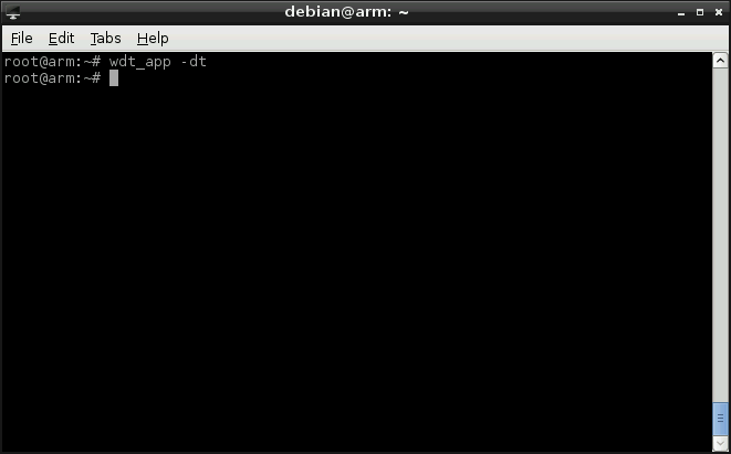
Figure 25: Disable WatchDog
Since the WatchDog is disabled, nothing will happen even though the timer counts down to zero.