5. Hardware Installation
5.1. Installing the P910-A Companion Card (optional)
The optional P910-A companion card is connected through CN1 & CN2 pin headers. Align and attach the board-to-board connector on the bottom of P910-A with the CN1 and CN2 blocks on the EPIA-P910 mainboard.
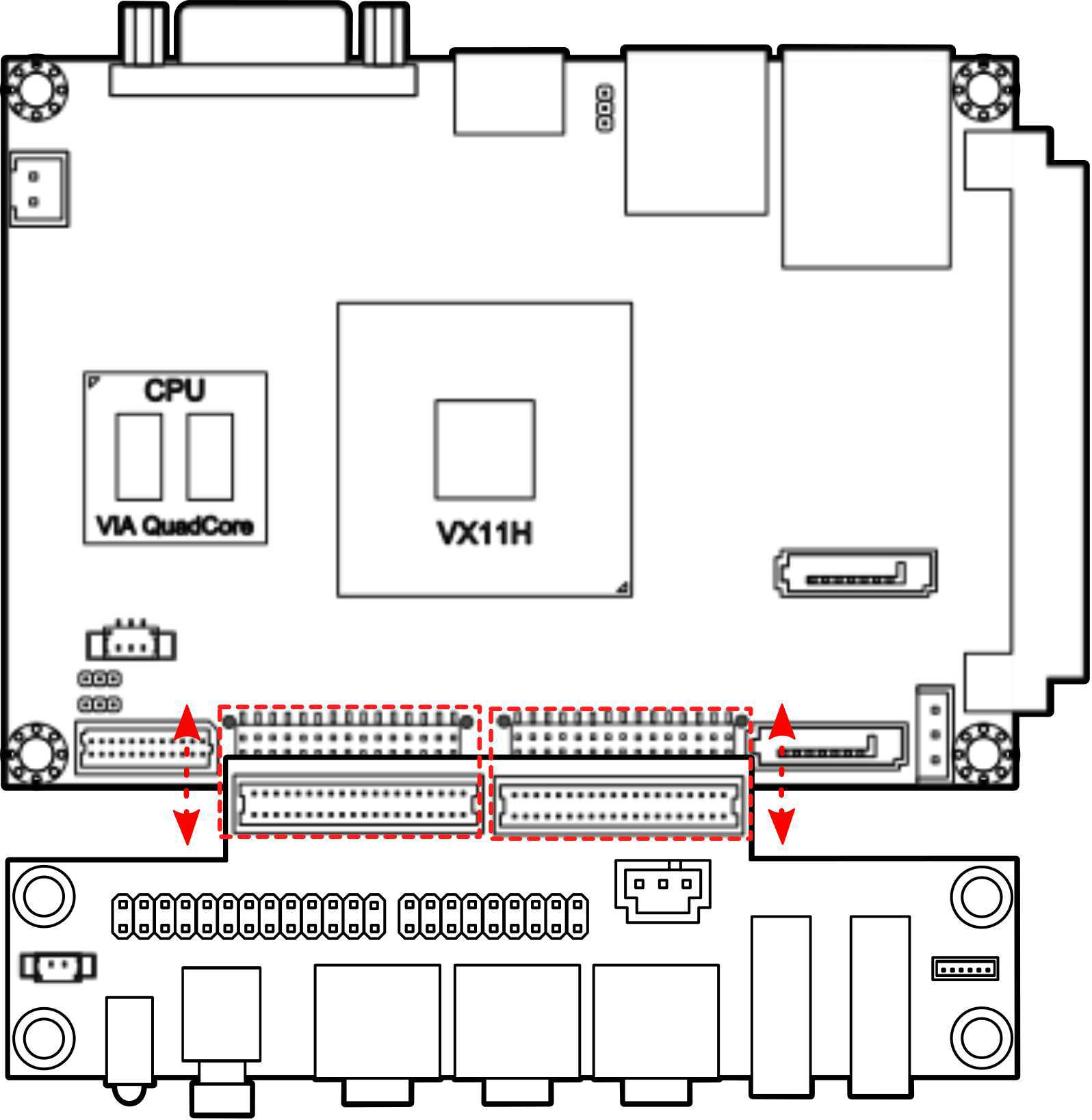
Figure 1: Connecting the P910-A companion card
Note
The P910-A companion card is for project based enquiries only. Please contact sales for detailed information.
5.2. Installing into a Chassis
The EPIA-P910 can be fitted into any chassis that has the mounting holes compatible with the standard Pico-ITX mounting hole locations. Additionally, the chassis must meet the minimum height requirements for specified areas of the mainboard.
5.2.1. Suggested minimum chassis dimensions
The figure below shows the suggested minimum space requirements that a chassis should have in order to work well with the EPIA-P910.
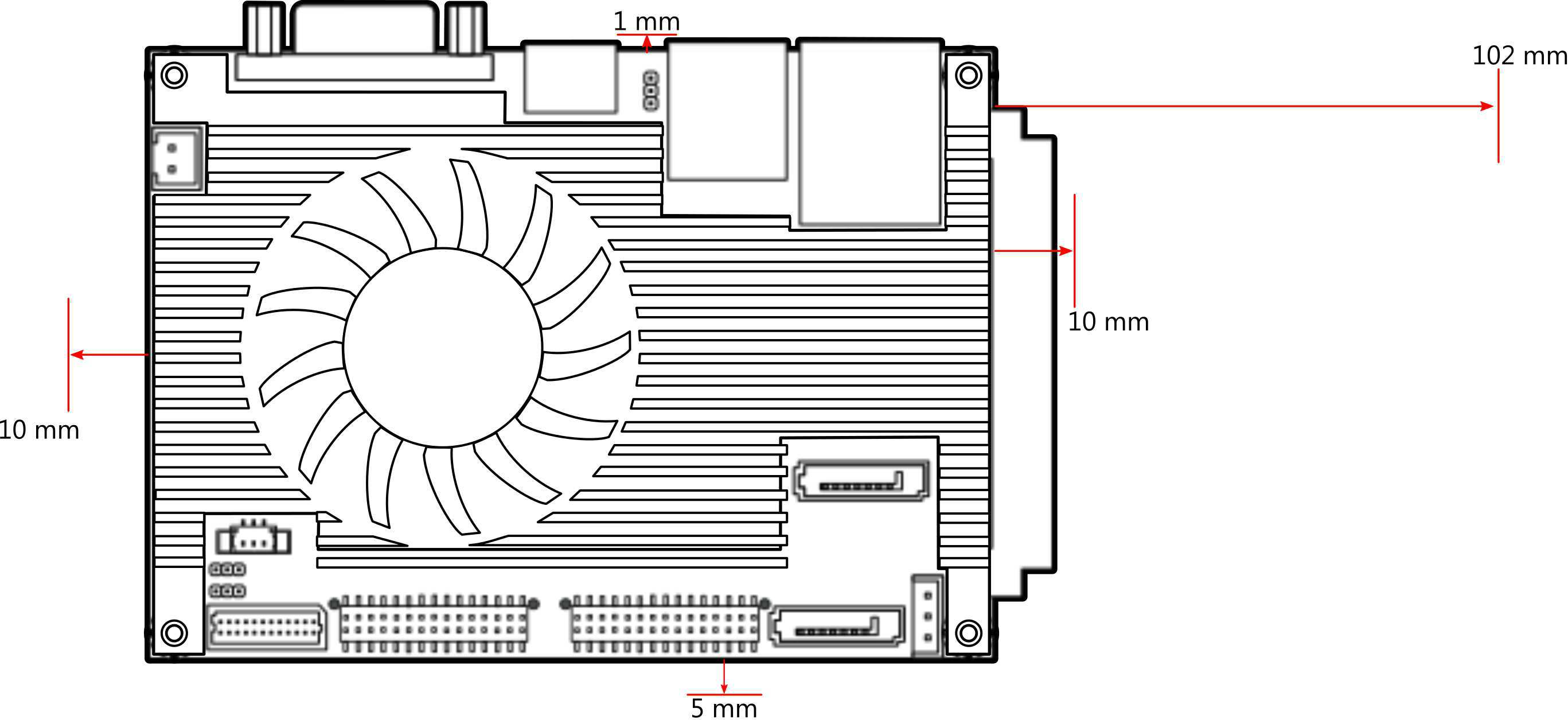
Figure 2: Suggested minimum chassis dimensions
Each side of the mainboard should have a buffer zone from the internal wall of the chassis. The side of the mainboard that accommodates the I/O coastline should have a buffer of 1.00 mm. The side on the opposite end of the I/O coastline should have a buffer of at least 5.00 mm. The two sides adjacent to the I/O coastline should have at least a 10.00 mm buffer.
5.2.2. Suggested minimum chassis height
The figure below shows the suggested minimum height requirements for the internal space of the chassis. It is not necessary for the internal ceiling to be evenly flat. What is required is that the internal ceiling height must be strictly observed for each section that is highlighted.
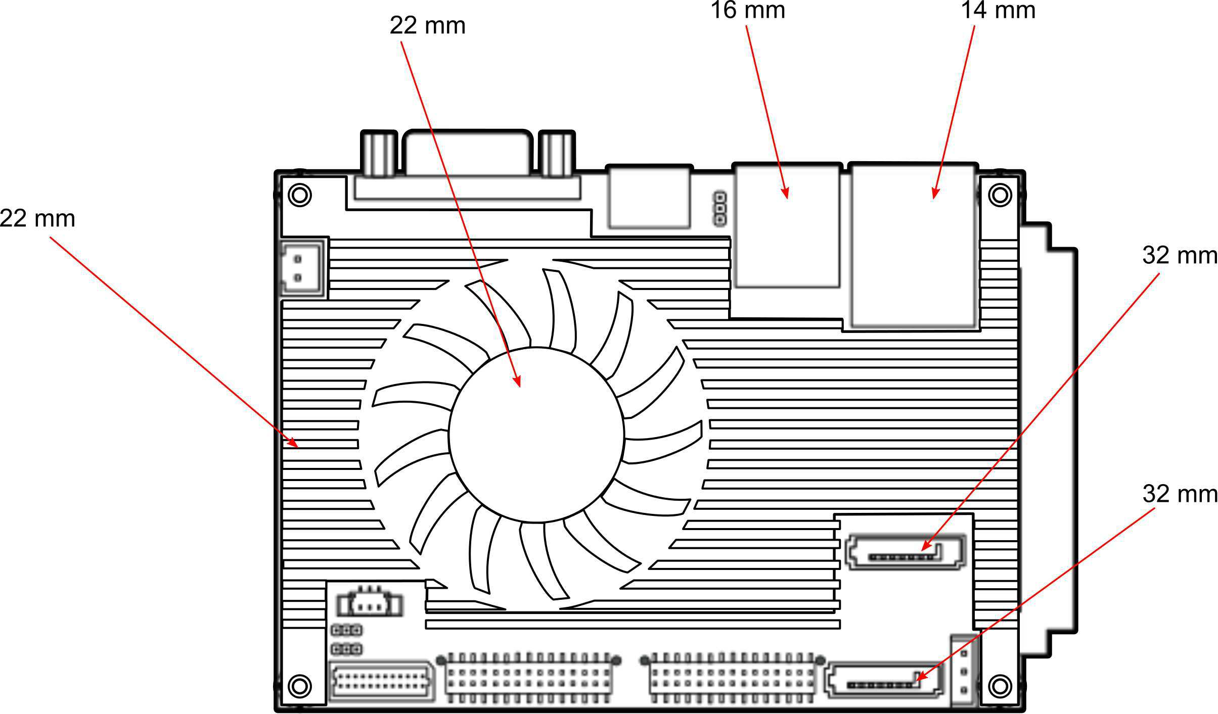
Figure 3: Suggested minimum internal chassis ceiling height
Note
In getting the minimum height requirements for internal space of the chassis, it is required to consider the heights of the connectors (such as SPI connector, CMOS battery connector and DDR3 SODIMM slot) on the bottom side of the EPIA-P910 mainboard.
5.2.3. Suggested keepout areas
The figure below shows the areas of the mainboard that is highly suggested to leave unobstructed.
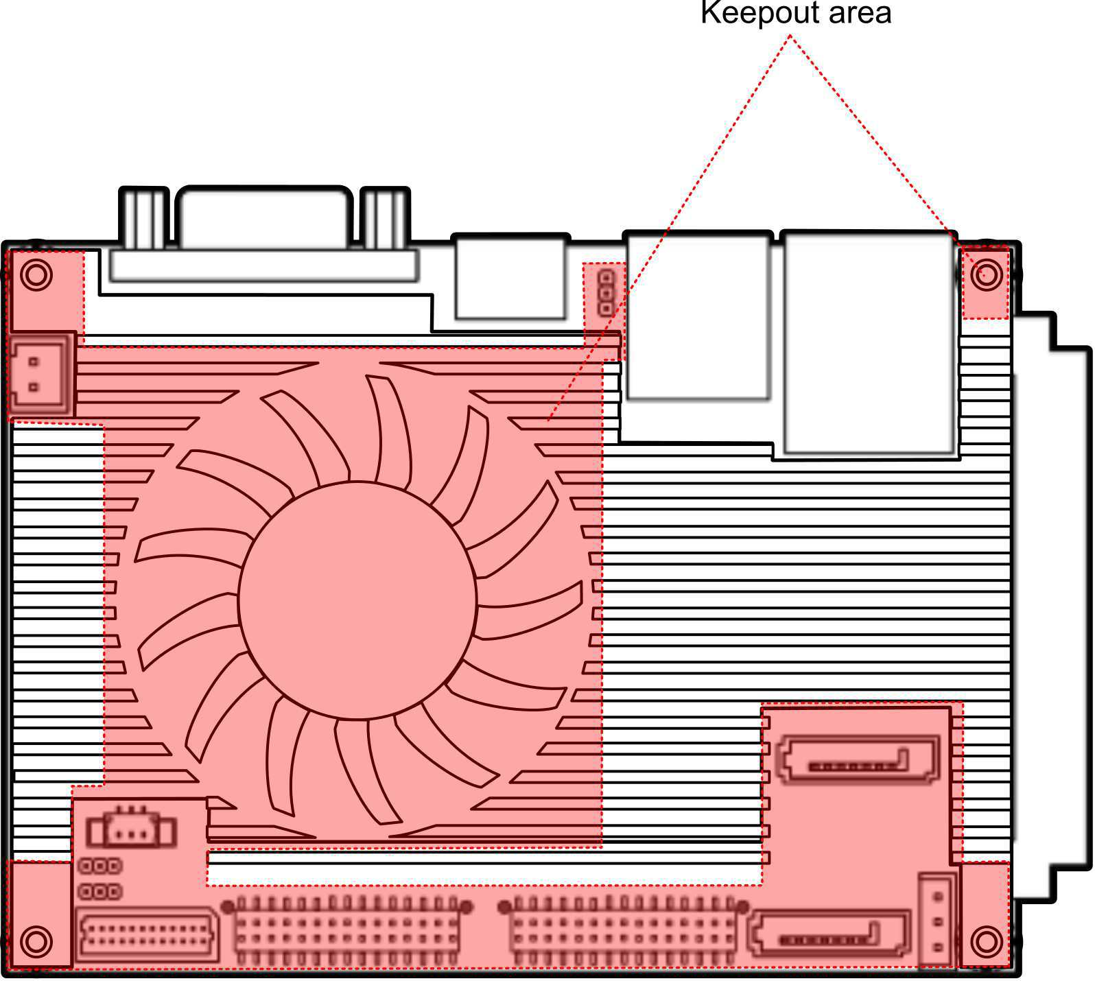
Figure 4: Suggested keepout areas