4. Expansion Slots
4.1. High Speed Extension Slot
The board-to-board slot labeled as “CN3” is a combination connector reserved for connecting to a customized expansion card. The connector pinout supports PCIe, LAN, USB 2.0, Audio, SDIO and SIM.
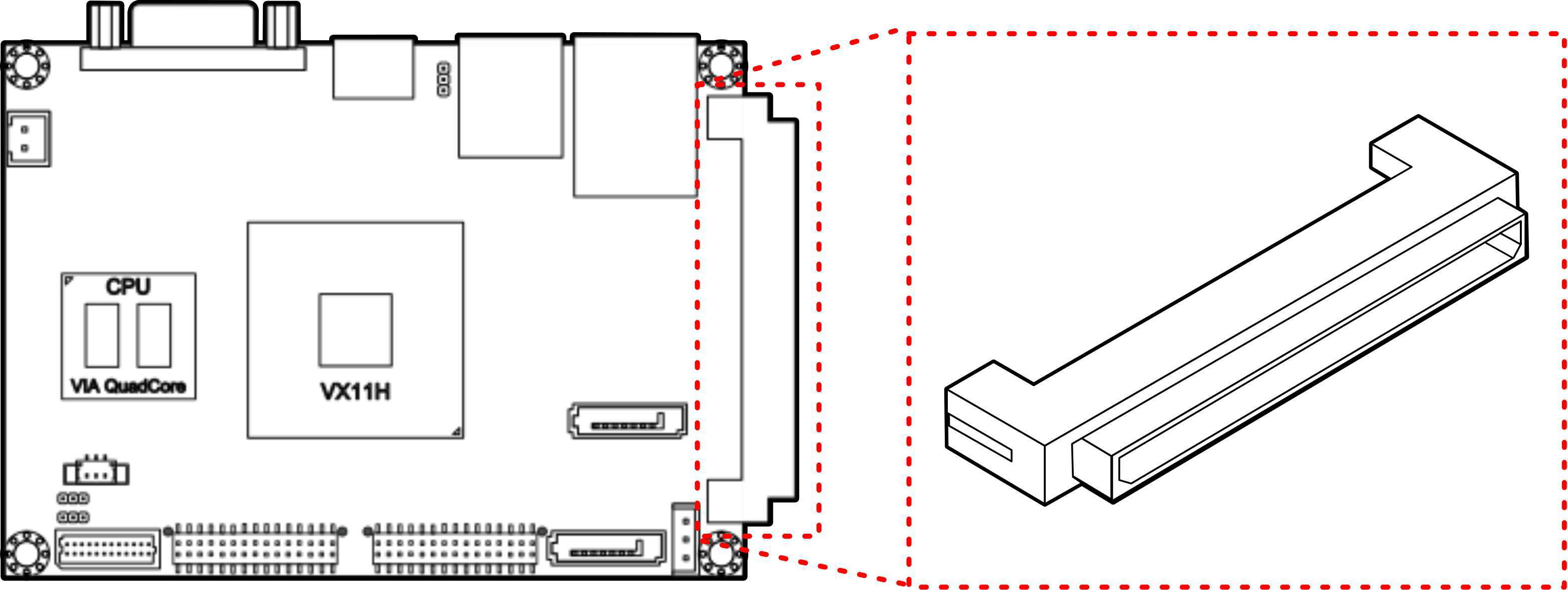
Figure 1: High Speed Extension tension Slot
High Speed Extension Slot pinout:
| Pin | Signal | Pin | Signal |
|---|---|---|---|
| 1 | +5VSUS | 2 | +5VSUS |
| 3 | +5VSUS | 4 | +5VSUS |
| 5 | +5VSUS | 6 | +5VSUS |
| 7 | +12V | 8 | +12V |
| 9 | GND | 10 | GND |
| 11 | GND | 12 | GND |
| 13 | GND | 14 | GND |
| 15 | TVCLKRIN | 16 | MICIN2_R |
| 17 | SPDIF_TX1 | 18 | MICIN2_L |
| 19 | MCVREF02 | 20 | LINE2_R |
| 21 | SENSE_B | 22 | LINE2_L |
| 23 | GND | 24 | GND |
| 25 | FANCTL2 | 26 | SPEAK_BZ |
| 27 | FANIN2 | 28 | GPIO37 |
| 29 | -PCIRST | 30 | -RING |
| 31 | RST_SW | 32 | SD_CLK/MMC_CLK |
| 33 | PW_BN1- | 34 | CR_CMD |
| 35 | -SUSC | 36 | CR_D7 |
| 37 | -SUSB | 38 | CR_D6 |
| 39 | -CR_CD | 40 | CR_D5 |
| 41 | -CR_WPD | 42 | CR_D4 |
| 43 | VCCCR | 44 | CR_D3 |
| 45 | CR_PWSELS | 46 | CR_D2 |
| 47 | CR_PWSEL | 48 | CR_D1 |
| 49 | CR_PWOFF | 50 | CR_D0 |
| 51 | GND | 52 | GND |
| 53 | -HD_LED | 54 | VREFOUT_E |
| 55 | -PWR_LED | 56 | DVPCLKN |
| 57 | LVDSPWM1 | 58 | DVPCLKP |
| 59 | DVPSPCLK | 60 | DVP1DE |
| 61 | DVPSPD | 62 | DVP1HS |
| 63 | SMBDT | 64 | DVP1VS |
| 65 | SMBCK | 66 | DVP1D11 |
| 67 | -PEREQ1 | 68 | DVP1D10 |
| 69 | -PEXWAKE | 70 | DVP1D9 |
| 71 | -PEX4RST | 72 | DVP1D8 |
| 73 | -PEX2RST | 74 | DVP1D7 |
| 75 | -PEX1RST | 76 | DVP1D6 |
| 77 | GND | 78 | DVP1D5 |
| 79 | USBHP3- | 80 | DVP1D4 |
| 81 | USBHP3+ | 82 | DVP1D3 |
| 83 | GND | 84 | DVP1D2 |
| 85 | PEXRX2+ | 86 | DVP1D1 |
| 87 | PEXRX2- | 88 | DVP1D0 |
| 89 | GND | 90 | GND |
| 91 | PETN2 | 92 | USBHP4- |
| 93 | PETP2 | 94 | USBHP4+ |
| 95 | GND | 96 | GND |
| 97 | PE6CLK- | 98 | USBHP2- |
| 99 | PE6CLK+ | 100 | USBHP2+ |
| 101 | GND | 102 | GND |
| 103 | PEXRX0- | 104 | PEXRX4- |
| 105 | PEXRX0+ | 106 | PEXRX4+ |
| 107 | GND | 108 | GND |
| 109 | PETN0 | 110 | PETN4 |
| 111 | PETP0 | 112 | PETP4 |
| 113 | GND | 114 | GND |
| 115 | PE1CLK- | 116 | PE3CLK- |
| 117 | PE1CLK+ | 118 | PE3CLK+ |
| 119 | GND | 120 | GND |
4.2. DDR3 SODIMM Memory Slot
The mainboard provides one 204-pin DDR3 SODIMM slot that supports non- ECC DDR3 1600/1333/1066 SODIMM memory modules. The memory slot can accommodate up to 8 GB of DDR3 1600/1333/1066 memory. The memory slot is labeled as “SODIMM1”. The location of the DDR3 memory slot is shown below.
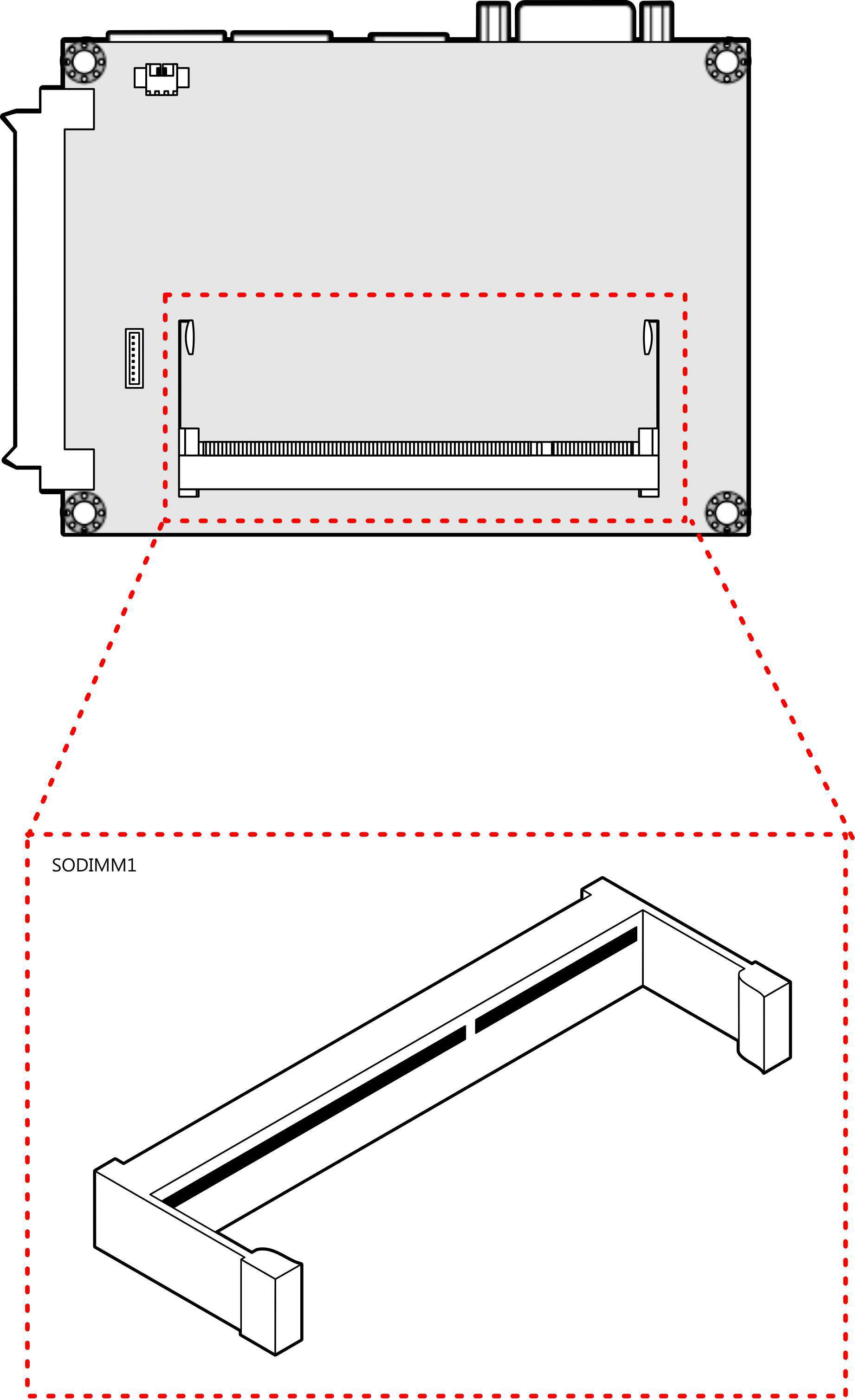
Figure 2: DDR3 SODIMM memory slot
4.2.1. Installing a Memory Module
Step 1
Align the notch on the SODIMM memory module with the protruding wedge on the SODIMM memory slot. Insert the SODIMM memory module at a 30 degree angle relative to the SODIMM memory slot.

Figure 3: Inserting the memory module
Step 2
Insert the SODIMM memory module between the two rows of pins. Then push down until the locking clips lock the SODIMM memory module into place. There will be a slight tension as the SODIMM memory module is being locked.

Figure 4: Locking the memory module
Step 3
Install the memory thermal pad on the top of the DRAM memory module.

Figure 5: Installing memory thermal pad
The memory thermal pad is used for transferring the heat dissipation of memory to the thermal plate or bottom plate to attain memory cooling, and to ensure the operating temperature of the memory module should not exceed to 85°C. This helps to prevent damage of the memory module. The memory thermal pad to be used is requires a certain thickness in order to make contact with the memory thermal plate or bottom plate to excellently disperse the heat.
Warning
- The customer/user should consider using the memory thermal pad and adding memory thermal plate or bottom plate on their chassis design.
- The memory thermal plate/bottom plate material to be used should have an excellent thermal conductivity. Avoid using plastic or rubber materials.
- The thickness of memory thermal pad should be based on customer’s design. However, the minimum value of thermal conductivity K (W/m.k) is 1.5 and the maximum of hardness is 5 (Shore A).
4.2.2. Removing a Memory Module
Step 1
To disengage the locking clips, push the locking clips horizontally outward away from the SODIMM memory module.

Figure 6: Disengaging the SODIMM locking clips
Step 2
When the locking clips have cleared, the SODIMM memory module will automatically pop up to the 30 degree angle. Remove the memory module.

Figure 7: Removing the memory module