5. Appendix A. Starter Kit
5.1. Starter Kit Assembly
The starter kit includes the following items:
- 1 x VAB-820
- 1 x VAB-820-A
- 1 x RTC battery
- 1 x AC adapter
- 1 x Power cord
- 1 x DC-in cable
- 2 x Transmittal cable
- 1 x Audio cable
- 1 x COM2/CAN converter cable
- 1 x 10.4” LCD panel including PCAP touch screen (optional)
- 1 x USB cable (optional)
- 1 x LVDS cable (optional)
- 1 x backlight power cable (optional)
5.2. Connecting the VAB-820-A
Firmly attach the 2 connectors J7A & J8A on the bottom of the VAB-820-A daughter board with the pin headers J7 & J8 on the VAB-820 mainboard. Then, plug one end of the transmittal cable to the COM connector on the VAB-820- A daughter board, and the other end of the transmittal cable to the COM connector on the bottom side of the mainboard.
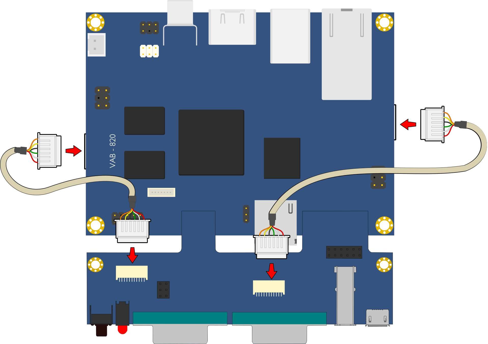
Figure 1: Connecting the VAB-820-A to the VAB-820 mainboard
The photo below shows the cable connections:

Figure 2: Cable connections
The photo below shows the panel connections:

Figure 3: Panel connections
5.3. VAB-820-A Specifications
- PCB Size
- 100 mm x 37 mm
- 4-Layer
- I/O Coastline
- 1 x Reset button
- 1 x power & WPAN/WWAN/WLAN LED stack
- 1 x COM1 D-sub 9-pin connector supports 8-wire DTE mode
- 1 x COM2 D-sub 9-pin connector supports 1 x COM2 (COM2 supporting 2-wire TX/RX) and 2 x CAN Bus (Supporting CAN Protocol specification Version 2.0 B) through a COM2/CAN converter cable
- 1 x USB2.0 connector
- 1 x Micro USB2.0 type B connector supporting OTG
- Onboard Connectors and Jumper
- 1 x CAN Bus jumper (J2)
- 1 x COM connector supporting 8-wire (J4)
- 1 x COM/CAN connector supporting 2-wire RD232 TX/RX and 2 FlexCAN TX/RX ports (J5)
- 1 x DIO pin header (4 INs and 4 OUTs)
- CAN Bus transceiver
- TI SN65HVD1050 EMC Optimized CAN transceiver
5.4. VAB-820-A Layout

Figure 4: VAB-820-A Layout (top view)

Figure 5: VAB-820-A Layout (bottom view)
5.5. VAB-820-A & COM2/CAN converter cable pinouts and jumpers
DIO
| Pin | Signal | Pin | Signal |
|---|---|---|---|
| 1 | – | 2 | – |
| 3 | GPO_1 | 4 | GPI_7 |
| 5 | GPO_2 | 6 | GPI_8 |
| 7 | GPO_4 | 8 | GPI_9 |
| 9 | GPO_5 | 10 | GPI_16 |
| 11 | GND | 12 | GND |
Reset
| Pin | Signal |
|---|---|
| 1 | RESET_N |
| 2 | GND |
| 3 | GND |
| 4 | GND |
J4
| Pin | Signal |
|---|---|
| 1 | – |
| 2 | COM_RXD1 |
| 3 | COM_TXD1 |
| 4 | COM_DCD1 |
| 5 | COM_RI1 |
| 6 | GND |
| 7 | COM_DTR1 |
| 8 | COM_CTS1 |
| 9 | COM_RTS1 |
| 10 | COM_DSR1 |
J5
| Pin | Signal |
|---|---|
| 1 | – |
| 2 | COM2_RX |
| 3 | COM2_TX |
| 4 | – |
| 5 | – |
| 6 | GND |
| 7 | CAN_RX2 |
| 8 | CAN_TX2 |
| 9 | CAN_TX1 |
| 10 | CAN_RX1 |
COM1
| Pin | Signal |
|---|---|
| 1 | COM_DCD1 |
| 2 | COM_RXD1 |
| 3 | COM_TXD1 |
| 4 | COM_DTR1 |
| 5 | GND |
| 6 | COM_DSR1 |
| 7 | COM_RTS1 |
| 8 | COM_CTS1 |
| 9 | COM_RI1 |
COM2
| Pin | Signal |
|---|---|
| 1 | CANH1 |
| 2 | COM2_RX |
| 3 | COM2_TX |
| 4 | CANL2 |
| 5 | GND |
| 6 | CANL1 |
| 7 | GND |
| 8 | CANH2 |
| 9 | VCC5 |
USBOTG
| Pin | Signal |
|---|---|
| 1 | OTG_VCC |
| 2 | OTG_DN |
| 3 | OTG_DP |
| 4 | USB_OTG_ID |
| 5 | GND |
USB
| Pin | Signal |
|---|---|
| 1 | USB3_VCC |
| 2 | USBD_T3- |
| 3 | USBD_T3+ |
| 4 | GND |
LED
| Pin | Signal | Pin | Signal |
|---|---|---|---|
| A1 | 3P3V | C1 | P_LED |
| A2 | 3P3V | C2 | LED_WLAN |
COM2/CAN converter cable
| CAN1 | |
|---|---|
| Pin | Signal |
| 2 | CANL1 |
| 6 | GND |
| 7 | CANH1 |
| 9 | VCC5 |
| CAN2 | |
|---|---|
| Pin | Signal |
| 2 | CANL2 |
| 6 | GND |
| 7 | CANH2 |
| 9 | VCC5 |
| COM | |
|---|---|
| Pin | Signal |
| 2 | COM2_RX |
| 3 | COM2_TX |
| 5 | GND |
Warning
Do not directly plug a COM connector to the COM2 connector. Please use the COM2/CAN converter cable when connecting to the COM2 connector