4. Hardware Installation
4.1. Installing into a Chassis
The VAB-820 can be fitted into any chassis that has the mounting holes compatible with the standard Pico-ITX mounting hole locations. Additionally, the chassis must meet the minimum height requirements for specified areas of the mainboard.
4.1.1. Suggested minimum chassis dimensions
The figure below shows the suggested minimum space requirements that a chassis should have in order to work well with the VAB-820.

Figure 1: Suggested minimum chassis dimensions
Each side of the mainboard should have a buffer zone from the internal wall of the chassis. The side of the mainboard that accommodates the I/O coastline should have a buffer of 1.00 mm. The side on the opposite end of the I/O coastline should have a buffer of at least 4.00 mm. The two sides adjacent to the I/O coastline should have at least a 10.00 mm buffer.
4.1.2. Suggested minimum chassis height
The figure below shows the suggested minimum height requirements for the internal space of the chassis. It is not necessary for the internal ceiling to be evenly flat. What is required is that the internal ceiling height must be strictly observed for each section that is highlighted.

Figure 2: Suggested minimum internal chassis ceiling height, top

Figure 3: Suggested minimum internal chassis ceiling height, bottom
4.1.3. Suggested keepout areas
The figure below shows the areas of the mainboard that is highly suggested to leave unobstructed.
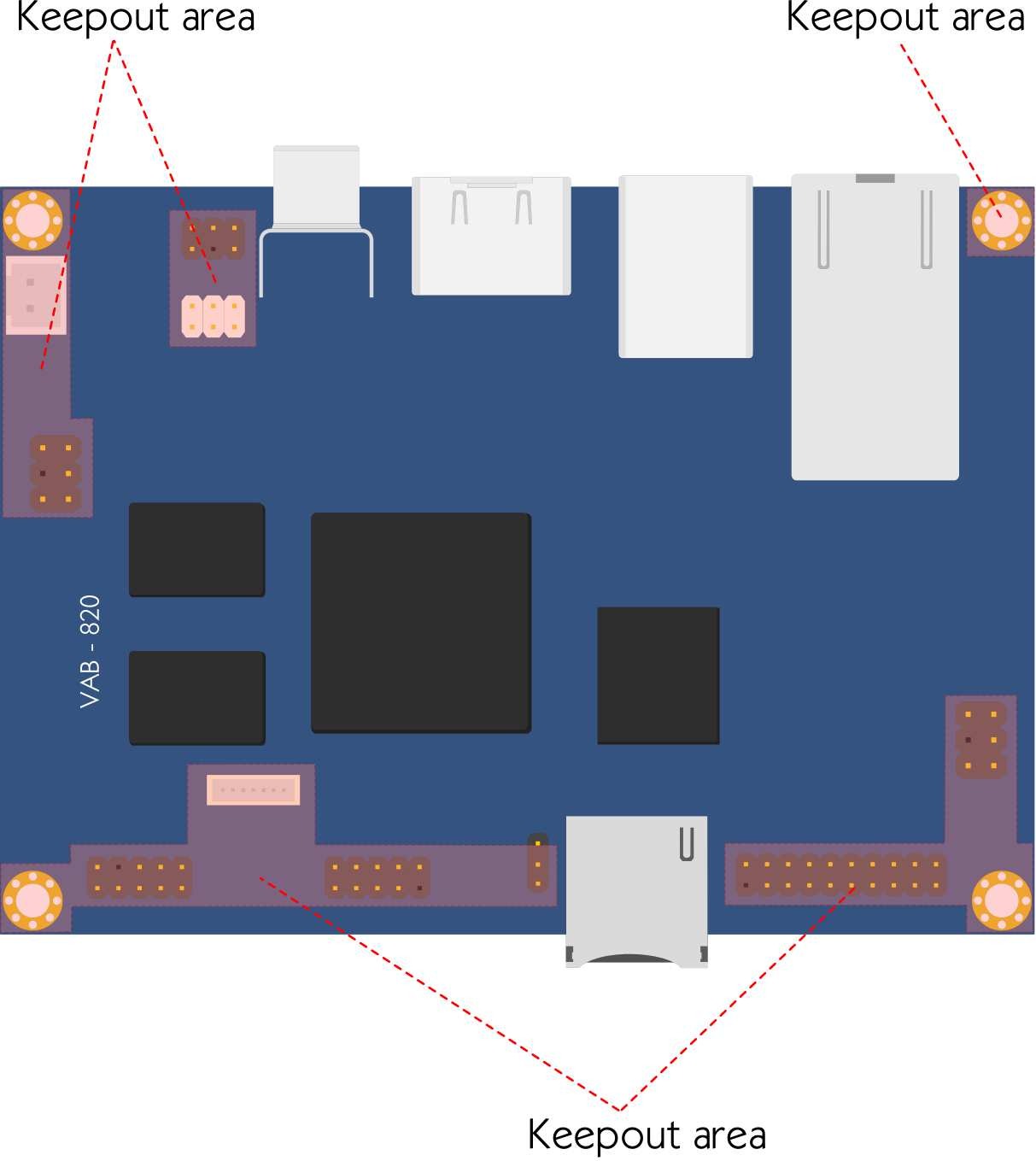
Figure 4: Suggested keepout areas, top
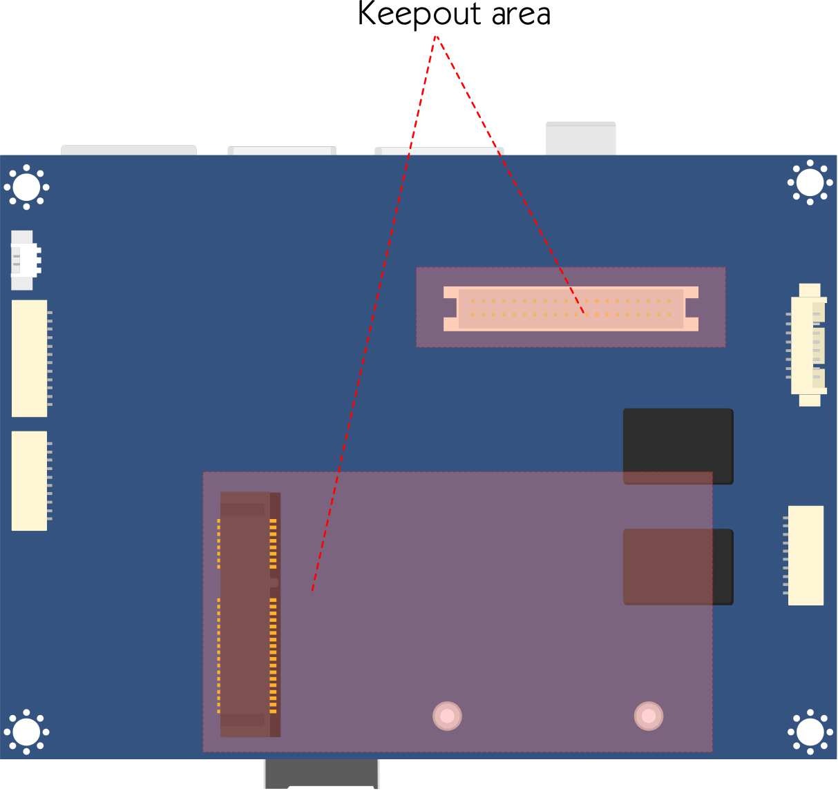
Figure 5: Suggested keepout areas, bottom
4.2. Installing the Mini-PCIe module
Step 1
Align the notch on the Mini-PCIe module with the counterpart on the Mini- PCIe slot then insert the module at 30° angle.

Step 2
Once the module has been fully inserted, push down the module until the screw holes align with the mounting holes on the hex spacer screws. Secure the module with two screws to the standoffs.

4.3. Installing the Heatsink (VAB-820 SKU)
Step 1
Align the heatsink over the three mounting holes. Use three washers and three M3 bolts to fix the heatsink.

Figure 8: Align the heatsink over the mounting points
Step 2
Secure the heatsink by tightening all the bolts firmly.

Step 3
Install the board to a system by using three M2 screws. For the unused mounting hole, use a M3 screw to secure it to the system.

Figure 10: Install the board to a system
4.4. Installing the Heatsink & PWB-P255-L PD power board (VAB-820-P SKU)
Step 1
Apply the thermal grease (about 0.06 cc) on top of the processor before installing the heatsink.
Step 2
Align the heatsink over the four mounting holes. Use two 10 mm bolts, one 11.7 mm bolts and one M3*6 screw to fix the heatsink on top of the board (please refer to the figure below for the placement). Secure the bolts and the screw with four M3 nuts on the bottom side of the board.

Figure 11: Installing the heatsink
Step 3
Align the PD power board over the heatsink, secure the PD power board to the bolts with three M3*6 screws. PoE connectors from the PD power board will be firmly inserted in the PoE pin headers of the VAB-820 board.

Figure 12: Installing the PD power board
Warning
When the PD power board is installed, connect the DC-in power jack to the DC-in power connector that is on the PD power board, not the one on the VAB-820