3. Jumpers
3.1. Clear CMOS Jumper
The onboard CMOS RAM stores system configuration data and has an onboard battery power supply. To reset the CMOS settings, set the jumper on pins 2 and 3 while the system is off. Return the jumper to pins 1 and 2 afterwards. Setting the jumper while the system is on will damage the mainboard. The default setting is on pins 1 and 2.
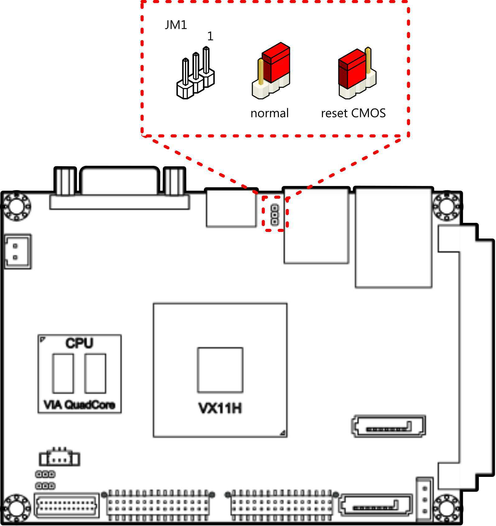
Figure 1: CLEAR CMOS jumper
CLEAR CMOS jumper settings:
| Setting | Pin 1 | Pin 2 | Pin 3 |
|---|---|---|---|
| Normal (default) | On | On | Off |
| Clear CMOS | Off | On | On |
Warning
Except when clearing the RTC RAM, never remove the cap from the CLEAR_CMOS jumper default position. Removing the cap will cause system boot failure. Avoid clearing the CMOS while the system is on; it will damage the mainboard.
3.2. Backlight Power Select Jumper
The mainboard has a jumper that controls the input voltage delivered to the LVDS inverter connector. The jumper is labeled as “JM2”. The jumper settings are shown below.
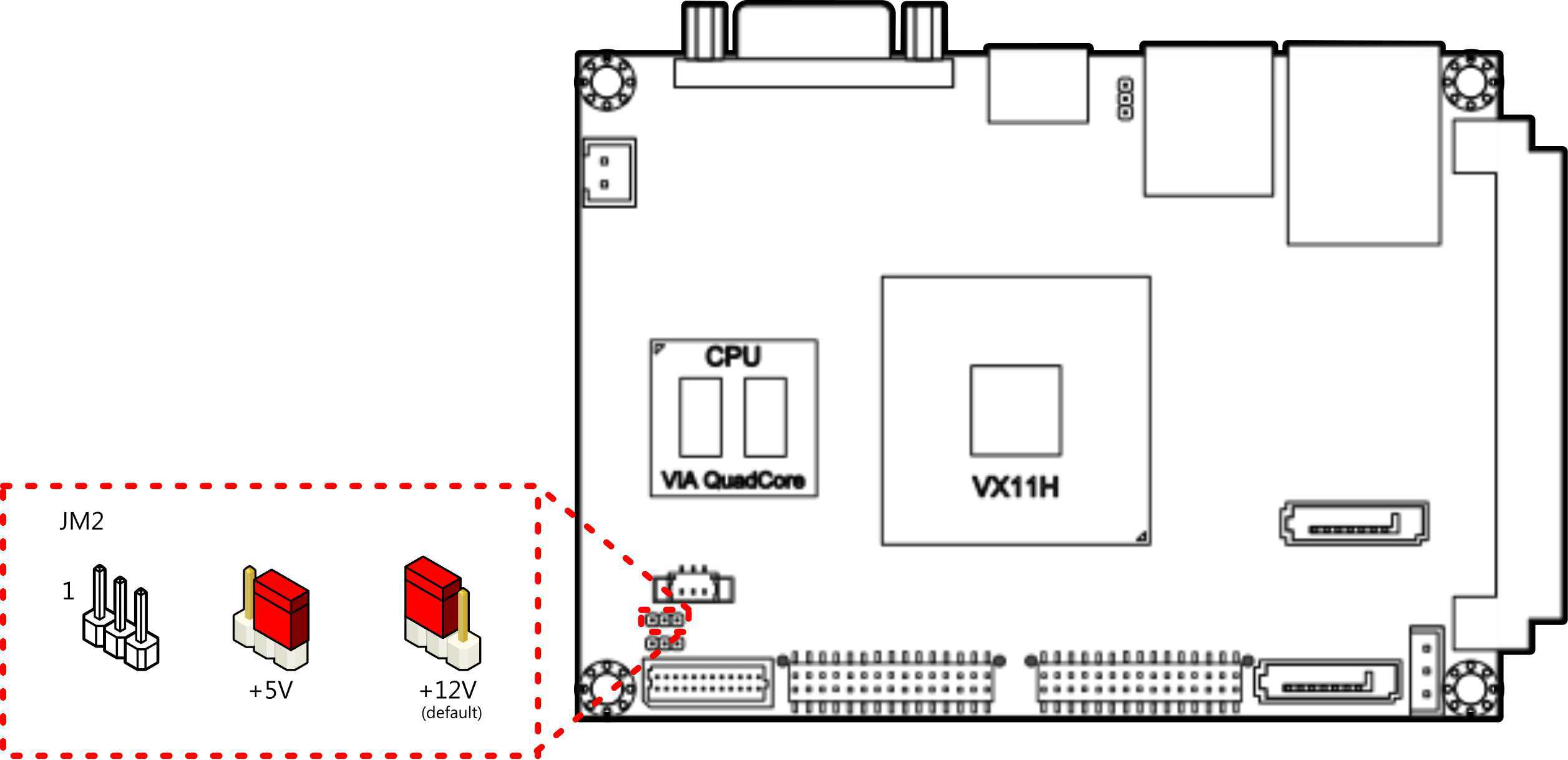
Figure 2: Backlight power select jumper
Backlight power select jumper settings:
| Setting | Pin 1 | Pin 2 | Pin 3 |
|---|---|---|---|
| +12V (default) | On | On | Off |
| +5V | Off | On | On |
3.3. Panel Power Control Jumper
The mainboard has one jumper that control the voltage delivered to the LVDS panel connector. The jumper is labeled as “JM3”. The jumper settings are shown below.
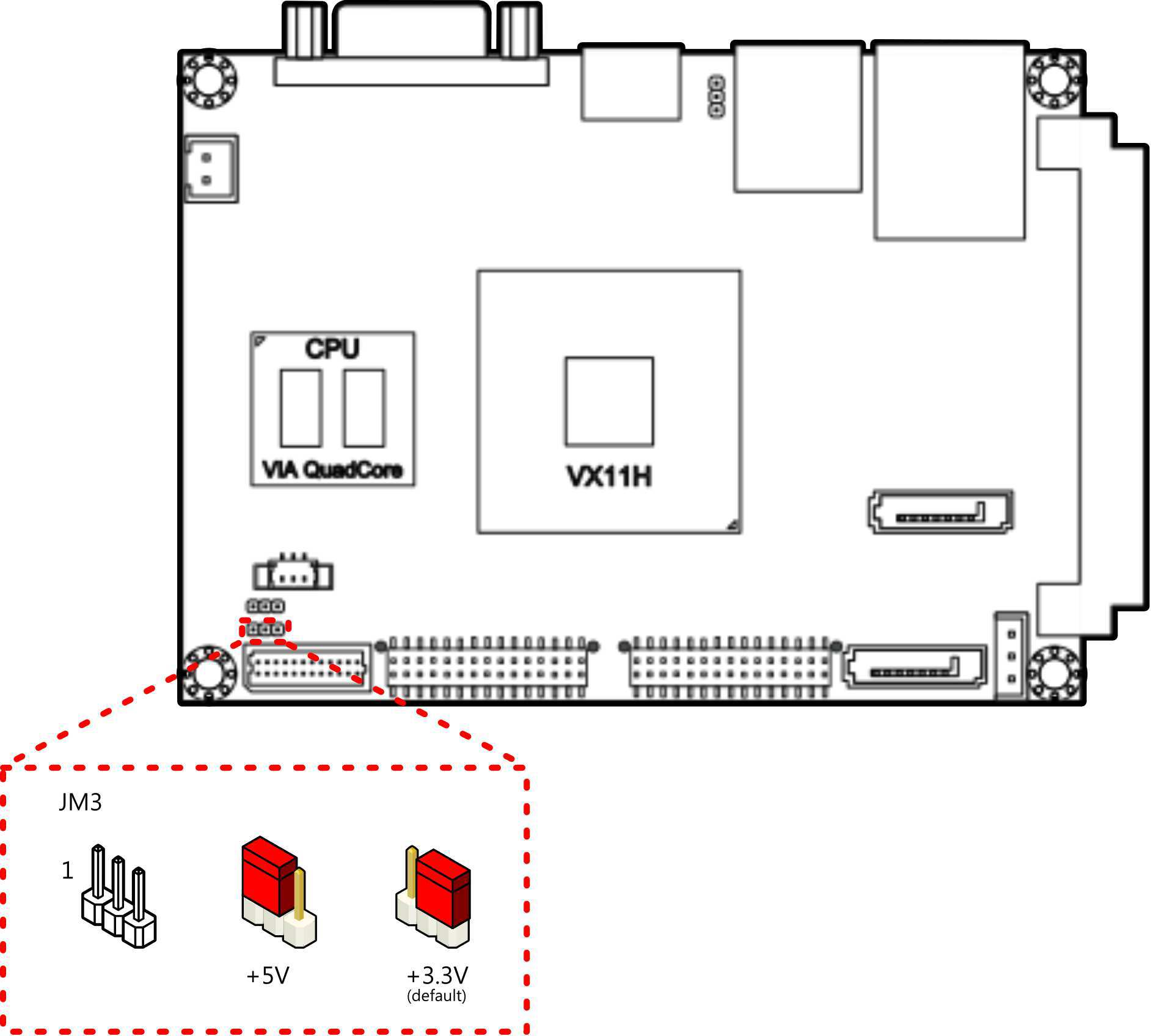
Figure 3: Panel Power Control jumper
Panel Power Control jumper settings:
| Setting | Pin 1 | Pin 2 | Pin 3 |
|---|---|---|---|
| +3.3V (default) | Off | On | On |
| +5V | On | On | Off |